Quantcast
Channel: Davide Gironi blog
Viewing all 198 articles
Browse latest View live

XinSound Fuzz FD-20 mod - Big Muff V2 Ram's Head clone

$
0
0

The XinSound Fuzz FD-20 is a Big Muff V2 Ram's Head guitar pedal clone.


It's schematic is next to the Electro Harmonix Big-Muff Pi 1975-15-10 original circuit.
As usually, I would like to experment on this pedal, doing some mods.


On the first and second gain stage of the original circuit, XinSound puts two soldered bridge to select which feedback loop diode and capacitors to use, a simple mod can be just split those bridge so try different sounds, it's the JP6 and JP7 bridge, you can see on the original board below.


The original electrolytics capacitors installed by XinSound where changed with Nichicon brand.
XinSound uses electrolytics capacitors on the clipping stage, but i prefer ceramic ones.
Also, all the four XinSound C1815 transistors where changed with classics 2N5088.
Below my modded board.


A Boost section it is added. The boost section produce an extremly clipped sound on bass.
One again many thanks to my friend Matteo for cutting me vinyl sticks for this pedal.
Found below the XinSound original schematic, as i've traced out, hope it does not contains errors.


And the modded one:


Notes
  • read risk disclaimer
  • excuse my bad english

The Happy Frog - A touch sensor switch

$
0
0

The Happy Frog is a simple single touch sensor switch.


It's high impedance switch, powered by a 9V battery.
The body can act as a switch, that close the circuit, now some current flow through the base of the NPN transistor, and the transistor makes current flow through the led.


One can use a two transistor in Darlington Pair to get more gain, and makes the led bright a little more.
Thank to my friend Matteo for the vinyl cut sticker


Notes
  • read risk disclaimer
  • excuse my bad english

A DIY A4 Laser Engraver made from a scanner and a printer on ATmega328

$
0
0

This "Get Ready For Win98" Laser Engraving Machine it's built using an old scanner, and an old printer.
A laser engraving machine is a tool that uses lasers to engrave an object.


I've an old broken scanner and an old printer lying around. Inspired by this instructables project:
http://www.instructables.com/id/Frankenstein-Laser-Engraver/
I decide to build a bigger version of my small CD-ROM based laser engraver, you can find here:
http://davidegironi.blogspot.it/2014/07/38mm-x-38mm-laser-engraver-build-using.html
That way, the engraving area are will be almost 212mm x 274mm.
Note that some part of this post is taken from the above blog post link.

Before starting up, read my blog disclaimer and the one below:

Warning! Laser diodes drive are emitting visible and invisible laser radiation and they are extremely dangerous! Their light can permanently damage the eyes. You must never look into the working diode even without the lens or point it on a reflective surface. Laser beam can cause burns or fire. This is usually a Class IIIb laser. Everything you do at your own risk.

The Y-axis it is build using the scanner assembly, the X-axis using the printer one.
As you can see by the Get Ready For Win98 sticker, the scanner is pretty old, and this sticker was so vintage that i've decided to leave it on.


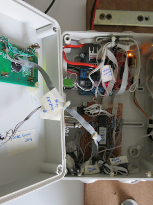
The base of this machine is the scanner itself.
The scanner was completely disassebled, all except the motor and the movement mechanism is removed. The same applies for the printer.
Assembling the hardware, pay attention to build it making X normal to the Y axis. The two direction has to be perpendicular, or your engraving will have distortions.
The printer mechanism it is connected to the Y-axis scanner assembly, that way, the laser moves over the part to be engraved.

My engraver it is powered by a 12V 2A power supply, though the total current absorbed it's 700mA.


The brain of this project is an ATmega328p running at 16Mhz. loaded with grbl firmware http://github.com/grbl/grbl, which is a powerfull yet opensource g-code parser.
I've used an Arduino Mini board, even if the software does not use the Arduino framework.
A 7805 voltage regulator it is used as power supply for the ATmega.
Grbl 0.9 it is build for 3 axis router, to make it works on 2 axis systems like this, with hard limit and homing enabled, a custom version of the firmware it is needed. The only change to apply to version 0.9g are on config.h file.
lines
#define HOMING_CYCLE_0 (1<<Z_AXIS) 
#define HOMING_CYCLE_1 ((1<<X_AXIS)|(1<<Y_AXIS)) 
was commented out and changed to:
#define HOMING_CYCLE_0 ((1<<X_AXIS)|(1<<Y_AXIS))
//#define HOMING_CYCLE_0 (1<<Z_AXIS) 
//#define HOMING_CYCLE_1 ((1<<X_AXIS)|(1<<Y_AXIS)) 
Then the new grbl firmware can be compiled and used, preventing grbl 0.9 homing problem on 2 axis machines.


My custom version of grbl v0.9g compiler for ATmega328p @16Mhz, with a baudrate of 115200, can be download below.
CP2102 it is used as USB to UART board.
You just have to upload the firmware using your favorite uploader, the grbl wiki page drive you on how to do this step.
On the grbl wiki page you could also find any other information about command and software setup.


The motor driver I've use to move the X and Y motor stepper are Polulu A4988 Stepper Motor Driver Carrier, based on Allegro A4988.
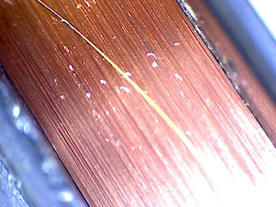
My scanner has an unipolar 5-wire stepper motor. That Allegro driver works only with 4-wire bipolar stepper motor. So I've transformed the unipolar motor to a bipolar stepper motor.
To made this modification, I've just cut the common wire between the two main windings. Then I checked that the windings haven't got any connection by using a multimeter. That way i have two coil, like a bipolar motor. Look at the image below for carify:


The printer has a bipolar 4-wire stepper motor.

We can setup how many microstep and how much current Allegro A4988 sends to the motor.
Incrasing microsteps makes the motor more accurate, but it also reduce the motor torque.
You can made some tests to find your best motor power setup.
For mine motors, to allow a smooth and fine motor movement, and a good torque the Allegro A4988 it is setup to 8 microsteps for the Y-motor, and 16-microstep for the X-motor.
Below you can find the basic Polulu board connection wiring.


To make the Polulu board runs at 8 microsteps M1 and M2 has to be connected to logic power supply VDD, if you want to run it at 16 microsteps, connect also M3 to VDD.

Motors supply VMOD is connected straight to 12v.

On each axis a limit and an home microswitch it is placed to prevent axis over-running, and eventually the motor or the motor driver damage.
Because the limit switch are pretty sensible to noise, I've added an high pass 100nF capacitor and an additional pull-up 10k resistor. Also the limit and home wire are indipendent and distant from the motor and laser cable strap.


The laser used is a red laser diode, taken apart from the DVD-ROM writer optics.
In CD-ROM and DVD-ROM you could also find IR driver, DVD laser writer diode will be a little more powerfull than the CD one.
Laser diode usually has three pins, one is the common ground, laser and photodiode cathode (-), one the laser diode anode (+), the other is the monitor photodiode anode(+).
If the diode you are using has no mark, and you do not know the diode pinout, you have to find the laser cathode and anode. One simple method I use is to power up the diode with a 1.8 to 2.2v current, just for a little amount of time, let's say 1s, if it absorbs current, that wiring is the laser diode pinout.

Laser diode has to be drive with a proper driver, to run mine, i've build a LM317 based laser driver.
This laser driver can drive diode from 12mW to 700mW.
A 9v voltage regulator prevent overvoltage on the laser diode.
Also a NPN it is placed to allow the TTL input that comes from the microcontroller to enable or disable the laser.
We are using LM317 IC as a current regulator.
Input voltage get in the Vin pin of the LM317, from the output Vout to the ADJ pin there is a resistor R connected.
The output current Iout is given by the formula Iout = Vref/R.
Over there resistor there always be Vref voltage. When current decrease, the voltage over R should be lower, but that way the regulator increase his output voltage to adjust his Vref voltage.
Vref is 1.25 for the LM317. R is made using a fixed resistor R1 and a trimmer R2. That resistor and the trimmer sets the current that the laser use.
So laser driver current is given by the formula: I=1.25/(R1+R3).
The power rating of the resistors R1 and R2 is calculated by the forumla P=1.25*I.
Before connecting the laser and testing the driver, check that the resistence is the higher value possible, then connect the laser and measure the absorbed current using an amperometer. Note that if you set too much current to the laser, that will blow.
Below the laser driver circuit.


A standard 60mm x 60mm pc brushless fan is installed to clear the smoke, this prevents the laser optics lens to be clouded.


Commands to the engraving machine are sent through UART at 115200 baud rate.

One you have built the machine, checked and connect all, upload the grbl firmware to your microcontroller, you could use terminal software, or a grbl controller to setup your board. I'm using Universal G-Code Sender to setup and send command to grbl, but you can also use a simple terminal.

The first thing to do is test the motor movement:

To test it, just send the
X10 Y10
command, or use the Universal G-Code Sender movement button.

You should see a motor movement on each axis.

Also check the laser is turned on and off using
M3
and
M5
command.

Now to setup the correct motor distance to run, you have to set each motor step/mm.
The axis motor step/mm calibration method is pretty simple.
Let's try the X axis calibration as example.
We know how many step/mm or steps_per_revolution grbl is actually setup, grbl $100=250.000 (x, step/mm) parameter.
Now, we move your motor for some steps, let's say 100 microsteps, the axis should have move 100mm.
Now we measure the real distance the motor has moved, let's suppose is 181mm.
The new step/mm value for this motor axis should be
steps_per_mm = (steps_per_revolution*microsteps)/mm_per_rev
so
138.121 = (250*100)/181
$100=138.121
Now, if you move the motor 100mm, it should move 100mm.

Because i've installed the limit and home switch, I have alse enabled hard limits
$21=1
I've setup the homing pull-off to 5mm, cause my microswitch have a long lever, and i want the motor to move fare away after the home cycle.
$27=5.000
Also the homing cycle it was enabled:
$22=1
And the homing direction mask it is changed. One may even need to invert axis direction, "dir port invert mask" is the paramenter you have to touch.

Those are the most common grbl setup, for the complete list, look at the grbl wiki page.

Below you can find the grbl configuration parameters i changed:
$21=1 (hard limits, bool)
$22=1 (homing cycle, bool)
$27=5.000 (homing pull-off, mm)
$23=3 (homing dir invert mask:00000011)
$100=37.879 (x, step/mm)
$101=94.246 (y, step/mm)
$110=100.000 (x max rate, mm/min)
$111=100.000 (y max rate, mm/min)
$130=212.500 (x max travel, mm)
$131=274.400 (y max travel, mm)

Now you could be able to send g-code drawing to your engraver.


There are a lot of software you could use to build g-code draw, the one I use the InkScape.
The working are for this plotter is 212mm x 274mm, so setup your project area to this dimension.
Once you have you path, then you could select the path you want to engrave, and transform it using the InkScape laser engraver extension.
Just copy the extension on your extension inkscape folder, restart inkscape, and use that to build your g-code file.
Once you have your g-code file, you could send it to grbl using Universal-G-Code-Sender, or other grbl software like Grbl Controller.


Code

Notes
  • read risk disclaimer
  • excuse my bad english

A Xively trigger PHP script to send email and SMS notifications

$
0
0
Xively is a platform devoted to simplifying the interconnection of devices and data with applications on the Internet of Things.


It uses feed and channels to collect user data. Any Xively channel can have one or more triggers. A trigger is a notification sent when a condition occurs on that channel.
For example if a channel is related to temperature. One can add a notification triggered when the temperature goes below a ceratin threshold.
Xively trigger does an HTTP POST request to an URL.
This is a PHP script one can use to send email and/or SMS alert for a Xively feed trigger action.

To use this script you have to upload it to any website running a PHP server.
Email are sent using the PHP mail function.
SMS are sent through a Betamax/Dellmont Voip provider. So, in order to be able to send SMS you must have some Dellmont voip account, and fill your credetils in the configuration zone of this script.
To prevent the notification of many SMS, a limiter functionality is implemented.
Also a sign it is used as a token to allow only the ones who know the token to use the script.

To use this script, point the Xively channel trigger post url to this script, and set the url parameter for your message.
As example, suppose you have installed the script at this address:
http://example.com/xivelytrig/xivelytrig.php
To send both mail and sms, use this url:
http://example.com/xivelytrig/xivelytrig.php?sign=example.com/xivelytrig/xivelytrig.php?sign=123456&feed=your_feed_name&channel=your_channel_name&alarm=your_alarm_text&address=address@example.com&mobile=000000000000
To send just email use this:
http://example.com/xivelytrig/xivelytrig.php?sign=example.com/xivelytrig/xivelytrig.php?sign=123456&feed=your_feed_name&channel=your_channel_name&alarm=your_alarm_text&address=address@example.com
Replace
 - 123456 with the $sign you set in your script
 - your_feed_name with then feed name you want to get for the notification
 - your_channel_name with then channel name you want to get for the notification
 - your_alarm_text with then message you want to get for the notification
 - address=address@example.com with the mail where to send the notification
 - 000000000000 with the mobile number where to send the notification


Code

Notes
  • read risk disclaimer
  • excuse my bad english

EnhancedBoxHelper .NET WinForm component helper

$
0
0
EnhancedBoxHelper is a open source enhanced component helper for .NET WinForm.


It's adds some advanced functions to an existing componente:
  • ComboBox
  • TextBox
  • DateTimePicker
by using the generetor helper.

It requires Microsoft Windows with .NET framework 4.0 or more.

It's basically a static class helper, that attaches events to a component.

One a TextBox you could attach the
  • Deselect on ESC press function: cleans the component if ESC key is pressed
  • Show the Helper form on Right click: show a popup form that lists a bounce of preselected values for the component
  • Show a Tooptip on Mouse Over: show a Tooltip that informs the user about the data selected
The ComboBox also has the
  • Deselect on ESC press function: cleans the component if ESC key is pressed
  • Show the Helper form on Right click: show a popup form that lists a bounce of preselected values for the component
  • Autocomplete on ENTER press function: autocomplete the selected item if ENTER key is pressed
  • Show a Tooptip on Mouse Over: show a Tooltip that informs the user about the data selected
DateTimePicker enhanchments includes :
  • Fast Select Key:
    • Press n or N to set now datetime
    • Press t or T or d or D to set today date
    • Press w or W to set the first, or last day of the week
    • Press m or N to set the first, or last day of the month
    • Press y or Y to set the first, o last day of the year
  • Move to the next datepart on / (slash) press
  • Interval helper on date selector. By setting a interval helper between two DateTimePicker, the user can select range of dates using some helpfull shortcut, or a combobox helper. The combobox attached to the helper can contains values that comply with the %d[d|w|m|y] regex. %d is a number, d stands for days, w for weeks, m for months, y for years. As example, if "+1d" is selected the To picker will be set as From +1 day, if "+2w" is selected the To picker will be set as From +2 weeks, and so on. A maximum interval number can be setted, so that the two pickers can never exceed that interval time. The date To select react to date From by custom fast keys:
    • Press CTRL + d or D on the From component will set the To to the same day of the From
    • Press CTRL + w or W on the From component will set the To to +1 week from the From
    • Press CTRL + m or M on the From component will set the To to +1 month from the From
    • Press CTRL + y or Y on the From component will set the To to +1 year from the From
The popup form uses the AdvancedDataGridView component you could find here.
Two small line are printed on the top right corner of any component attached by the autocomplete helper windows. The color of the two lines can be overriden on the static class.

The most of the time one should attach all the helper provied.
Using the attacher helper method is quite simple, you can find a few example in the sample project and a little sample snippets below.

//Sample attachment function
EnhancedComboBoxHelper.AttachComboBox(
  comboBox1,                                    //target component
  new string[] { "Name", "Address" },           //header for autocomplete Form
  _users.ToList().OrderBy(r => r.name).Select(  //load the list for autocomplete Form
    r => new EnhancedComboBoxHelper.Items()
    {
      _id = r.id,                               //id of selection
      _value = r.name,                          //show value
      _values = new string[]                    //values listed
      {
        r.name,
        r.address
      }
     }).ToArray());

//Sample attachment function
EnhancedComboBoxHelper.AttachComboBox(
  comboBox1,                                    //target component
  new string[] { "Name", "Address" },           //header for autocomplete Form
  _users.ToList().OrderBy(r => r.name).Select(  //load the list for autocomplete Form
    r => new EnhancedComboBoxHelper.Items()
    {
      _id = r.id,                               //id of selection
      _value = r.name,                          //show value
      _values = new string[]                    //values listed
      {
        r.name,
        r.address
      }
   }).ToArray(),
   EnhancedComboBoxHelperList.ViewMode.SelectOnDoubleClick,    //selection mode, how the autcomplete Form selection changes is treated
   () => MessageBox.Show(comboBox2.SelectedValue.ToString())); //selection mode action, get's called after the selection on the autcomplete Form changes 

//Sample attachment function
EnhancedDateTimePickerHelper.AttachDateTimePicker(
  dateTimePicker1,                              //target component
  "yyyy/MM/dd");                                //custom format

//Sample attachment function
new EnhancedDateTimePickerHelper.FilterDateHelper(
  dateTimePicker2,                              //target component from
  dateTimePicker3,                              //target component to
  null,                                         //actions to run after the date is changed
  comboBox3,                                    //fast day combobox selector
  365,                                          //max days between from and to date
  DayOfWeek.Monday,                             //first day of the week
  EnhancedDateTimePickerHelper.FilterDateHelper.FromPickerDefaultValue.FirstDayOfWeek,    //select the default day for from datetimepicker
  EnhancedDateTimePickerHelper.FilterDateHelper.ToPickerDefaultValue.FromPickerSameDay);  //select the default day for to datetimepicker


Code

Notes
  • read risk disclaimer
  • excuse my bad english

A generic C# data access layer built on top of the Entity Framework

$
0
0
The Entity Framework is the Microsoft official ORM (Object-Relational Mapping) framework.


This library implements the Repository Pattern. It's mask the detail of the Data Access Logic from the Business Logic using Repositories.
Repositories are build on top of Entities using C# generics.
Repositories offers a few methods to perform CRUD operations (Create, Read, Update, Delete) and other SQL operations like MAX, MIN...
An instance of the entity framewor context class is created for each operation.
Each repository implements an interface that provides methods to performs operation on an entity object of the model.
You can access any repository by the main model instance. Each repository will be instantiated at the model construction.
Any repository method can be overriden.
The main model class implements the a generic class and defines each repository as a public property.

The main methods you will find on repository are:
  • List: load an entities with records
  • Find: load an entities searching for key values
  • Add: add records to the underlying database
  • Update: update records of the underlying database
  • Remove: remove records from the underlying database
The List method filter values by the use of a predicate.
The generated LINQ query is then translated to SQL by the Entity Framework engine.
The Find method implements the Find LINQ method.
Add, Update and Remove methods perform the SQL INSERT, UPDATE and DELETE operations.

Three methods should be overridden almost every time a Repository is implemented:
  • CanAdd: check if entities can be added
  • CanUpdate: check if entities can be updated
  • CanRemove: check if entities can be removed
Those methods should be called before the main Add, Update and Remove operations to check for entites consistency.

Other SQL/LINQ operators are implemented in the repository, like:
Any, FirstOrDefault, Average, Order, Count, LongCount, Max, Min, Remove, Sum.

A LanguageHelper class provides usefull methods to internationalize String fields used in repositories. Those fields can be used to localize errors message for repository methods.

A few lines of codes are enough to implemt a fully loaded model.

This project is as always release open source. You can find source code, on the github.com link above.
The code also contains a sample model, and a few UnitTest to check against it.


Code

Notes
  • read risk disclaimer
  • excuse my bad english

Behringer v-tone GMX212 Hybrid tube amplifier mod

$
0
0

Some time ago I've repaired a Behringer v-tone GMX212 http://davidegironi.blogspot.it/2012/01/behringer-v-tone-gmx212-repair-bypass.html
That was the first post of this blog.

Now I would like to mod this amplifier, switching is original preamplifier board with a custom one.
This mods dives me in the vacuum tube world.

WARNING! - The project described in these pages utilizes POTENTIALLY FATAL HIGH VOLTAGES. Do not attempt to build circuits presented on this site if you do not have the required experience and skills to work with such voltages. I assume no responsibility whatsoever for any damage caused by the usage of my circuits.


To improve my knowledge on tube amplifiers, I've read articles from two really well written website: http://www.valvewizard.co.uk/ and from http://www.ax84.com/.

For this project I've used 12AX7 vacuum tube. This tube is one of the most used for the guitar preamplification. So there are many resources available on web.
The first problem i faced it's the power stage. Tubes needs high voltage in order to work properly. The solution I've found was to connect a 230V/9V power transformer with secondary and primary reversed. That way, connecting it to the 10.5V AC output of the main Behringer transformer i can get almost 160V DC.
Any tube also needs a low voltage current to power up the heater. I choose to use a 7805 voltage regulator, shifted by 1.3 volts using two switching diodes. This gives me the 6.3V DC I need.


The preamplifier circuit it's next to the AX84 P1 Guitar Amplifier, the tube load and ground resistor where changed to fit the load line of my tube for my power voltage. You have to calculate your own values it you use other voltage.
As a tone circuit, I've selected something similar to the Fender Tweed Princeton one.


The Behringer v-tone GMX212 has many output and input on the back that i do not want to lose.
To keep the back ports and to reach the amplifier board with correct voltage, I've built a connection boards that levels the preamplifier input like the original Beheringer preamplifier board does.
I've just measured levels coming out from the original board, and reproduced my version of that circuit using two TL072 opamps to adapt my preamplifier levels.


Eventually I would like to add some sort of reverb effect to this amplifier. So I've try the PT2399. What I've built it isn't really a reverb, it's more an Echo/Delay. But it's an interesting ambient effect i would like to have on this amplifier.
The reverb board use on TL072 to mix the wet and dry signal without any lose.


The amplifier stage is the original Behringer v-tone GMX212 one.

The amplifier plate log was replaced by a new one, engraved with my homemade laser engraving machine: http://davidegironi.blogspot.it/2015/12/a-diy-a4-laser-engraver-made-from.html


That's all for this amplifier... until the next modification.

12AX7 guitar preamplifier and power supply board:


Schematics of the PT2399 delay/reverb board:


Schematics of the mix level board:


Notes
  • read risk disclaimer
  • excuse my bad english

DigiTech MC7 MIDI Controller Pedal repair

$
0
0
The DigiTech MC-7 MIDI Controller Pedal is a standard MIDI program change device.


The MC-7 transmits 1-128 program changes on 1-16 MIDI channels.
I've buy this JUN'91 pedal used for a few Euros. It has a problem on the "c" segment of any of the four 7-segment display.
The repair was quite simple. The integrated 7-segment display lines are driven by  through a 74HC574 octal D-type flip-flops. Signal goes by the 74HC574 through 8 resistors in the 7-segment display.


It takes a few minutes to find which was the "c" segment output signal, simply changing the output channel to display or not that line. Once i've done it, i've checked if the signal goes in to the display... and BINGO!... for the "c" signal it get's interrupted on the soldered join of the display. It's the last join on the right of the below picture.


I just soldered it back, and the display keep working. As you can see.
Pretty simple.
Just for those you are interested, that's the refresh timing for that display.


Adding a cheap USB to MIDI adaptor gives this '91 pedals takes this pedal "Back to the Future".

Thank for Paolo that sells me this pedal board, and a thumbs up to DigiTech support that sends me the 4 pages manual for this pedal, just for completeness.


Notes
  • read risk disclaimer
  • excuse my bad english


A CNC Pickup Winding machine built on an ATmega8

$
0
0

A pickup winding machine it is used to wind a guitar pickup.
You can find my previous ATmega manual pickup winding machine here: http://davidegironi.blogspot.it/2014/05/a-pickup-winding-machine-built-on.html
This project is a manual / CNC pickup winding machine, built on top of an ATmega8 microcontroller.


Characteristics:
  • wind counter
  • slow startup
  • automatic stop
  • configurable motor speed
  • configurable winds
  • 2 direction
  • CNC automation
  • configurable wire dimension (for CNC)
  • traverse dynamic speed
This winder has an LCD display, it will show:
  • the current motor direction
  • the rotating speed of your pickup
  • the total and current wind counter
  • the direction of the traverse mechanism
  • the speed of the traverse motor
User can choose if enable or not the guide movement, if not, this machine can be use in manual mode.

There are 3 buttons, SELECT, button UP and DOWN.
Short press SELECT to move to make the traverse motor move 1mm.
Long press SELECT to enter / exit programming mode. During the programming mode press button UP and DOWN to edit the selected value, short press SELECT to skip the next value, or long press SELECT to save new values and go back to running mode.
Short press button UP to change direction of the winding.
Long press button UP to reset counter.
Short press button UP to change direction of the guide movement.
Long press button DOWN to reset counter.


If you are in building mode, to make the wind start press the RUN pedal, it will start with a slow startup, to stop the winder release the RUN pedal.

The winding machine will automatically stops when the wind counter reach the configured number.
If you disable the autostop mode, the machine will always count wind, independently by the direction choosen.

The winding motor used is cheap DC motor 12V 1200rpm, the motor driver is L298N chip board.


The traverse mechanism it is built using parts from a (broken) scanner, the guide motor is the stepper motor of the scanner.


Traverse mechanism has two limits. Limits are build using break-beam optosensos mounted on a small cilindric neodymium magnet.
That way guide limits can be moved depending on the pickup to be wired.


The wire tensioner it build using felts and a spring. It is simple but it works quite good.

The winding nozzle it's taken apart from a dental saliva ejector that my father (who is a dentist), gives me. It has a really small hole, and it's also built with plastic. This will not damage the wire we are going to wind.


The counter sensor it is built using a hall effect switch and a small neodymium magnet glued to the pickup holder.

My traverse mechanism has an accuracy of 5.29 um/step. One can mount another guide motor and harware, and will have other accuracy, indeed that mechine need to be calibrated.

Whenever the guide mechanism is changed, those constants has to be set GUIDEMOTOR_1STEPUM, GUIDEMOTOR_1MMSTEP, GUIDEMOTOR_1CMMAXSPEEDTIMEMS, GUIDEMOTOR_1CMMINSPEEDTIMEMS, GUIDEMOTOR_FIXEDSPEED_DEFAULT, WIRE_MINGAUGE, WIRE_MAXGAUGE

There are two calibration steps the user has to do:
  1. Measure the traverse distance moved per step. The GUIDEMOTOR_MEASURESTEP directive has to be set to 1, and the number of step to move has to be set in GUIDEMOTOR_MEASURESTEPSTEPS. Then the hex has to be compiled and uploaded. Now when you startup the machine, the guide will move for the desired number of steps. We measure the distance traveled. We compute the steps/mm as steps moved / total distance traveled. Than um/step is 1000 / steps/mm. Let's suppose we have set 20000 as step to move. If we have measured a traveled distance of 106mm, the step/mm is 188.879, and um/step is 1000/188.879, so 5.29. When done, set GUIDEMOTOR_MEASURESTEP to 0 again. Now we can set GUIDEMOTOR_1MMSTEP to step/mm value and GUIDEMOTOR_1STEPUM to um/step value.
  2. Measure the traverse maximum / minimum speed. The GUIDEMOTOR_MEASURESPEED directive has to be set to 1. Then the hex has to be compiled and uploaded. Now when you startup the machine, the LCD will show the max and min speed the guide motor takes to move 1cm. When done, set GUIDEMOTOR_MEASURESPEED to 0 again. Now we can set GUIDEMOTOR_1CMMAXSPEEDTIMEMS and GUIDEMOTOR_1CMMINSPEEDTIMEMS to the values shown on the display.
After that calibration steps is been execute, other values has to be set.
A guide step helper spreadsheet it is provided to help compute that values. The GUIDEMOTOR_FIXEDSPEED_DEFAULT, WIRE_MINGAUGE and WIRE_MAXGAUGE dimensions can be computed using this sheet.
You just has to fill values you already know, the values of your hardware.

The math to compute that values is also described as comments in the source files.

The maximum and minimum wire gauge it is an important parameter that defines what your pickup winder can wrap.

The winding pattern implement in this machine, is a simple traverse winding that places each wire wind next to the previous one.
See below and example of a pickup winded with this machine.


Things get's intereseting here, because the wiring motor doesn't always spin the same speed, take as example the "slow startup" stage, or when you decide to wire your pickup at a lower speed.

The guide motor is driven in a TIMER interrupt.
Here we set the steps that motor walk to position the cable,
We know:
  • the number winds made from the last motor movement
  • the current pickup rotation speed
  • the wire gauge
  • how many distance the guide motor travel for every step done
  • the maximum and minimum time the guide motor takes to walk 1cm

We can compute how much space the traverse mechanism has to travel in order to place the wire next to the previus one, that's pretty simple.

number_of_winds = current_number_of_winds - current_number_of_winds
distance_to_wire = wire_gauge * number_of_winds
step_to_move = distance_to_wire / guide_motor_distance_traveled_for_1_step

Things get's a little complicated because i'm not using float math, so i've to record the remnant of the division.

number_of_winds =
  current_number_of_winds - current_number_of_winds
distance(um)_to_wire =
  wire_gauge(um) * number_of_winds + remntant_distance(um)_to_wire
step_to_move =
  distance(um)_to_wire / guide_motor_distance(um)_traveled_for_1_step
remntant_distance(um)_to_wire =
  distance(um)_to_wire % guide_motor_distance(um)_traveled_for_1_step

But that's not all folks, we also have to move the guide motor at such a speed that every wire is placed next to the other right when the pickup has done a full loop, I mean, we do not want a rapid guide motor travel, then a motor stop, then a rapid travel again, that movement has to be continous, and smooth, related to the pickup winding speed.

So, let's try to estimate that guide motor speed.

rotation_per_seconds = motor_rpm / 60
distance(um)_to_wire_in_1second = rotation_per_seconds * wire_gauge(um);
time(ms)_to_wire_1cm = (10000*1000) / distance(um)_to_wire_in_1second;

Now, the trick here it that we have previously recorded the maximum and minimum time in ms that the guide motor takes to move 1cm, so we can map the time we need, with that max and min speed.

speed = 100 - (time(ms)_to_wire_1cm - GUIDEMOTOR_1CMMAXSPEEDTIMEMS) * (100 - 1) / (GUIDEMOTOR_1CMMINSPEEDTIMEMS - GUIDEMOTOR_1CMMAXSPEEDTIMEMS) + 1;

That way we obtain a speed value from 1 to 100 for the guide motor to run smooth.

Enabling GUIDEMOTOR_DEBUGSTEPANDSPEED will display the current speed and steps left to run for the guide motor. This is a usefull during the debug stage. The speed will never exceed 100, and the steps left will never grow up. It it happens, it means that the guide is going too slow.


Future improvements will be implement an UART protocol to drive this machine by a PC, that way multiple wiring pattern can be simply performed.

This project was developed on Eclipse, built with avr-gcc on ATmega8 @ 16MHz.


Code

Notes
  • read risk disclaimer
  • excuse my bad english

Joyo Vintage Overdrive mod - Tube Screamer clone

$
0
0

The Joyo Vintage Overdrive JF-01 is a Tube Screamer guitar pedal clone.


I've checked it against the TS-808 Tube Screamer schematic, and what I've found is that it has the circuit, it also has the same components values of the Tube Screamer.
Indeed, at least to my ear, it's sounds like a TS-808.


But, because i would like to experiment a little, i apply some mod on this pedal.
I've basically given a little more distorsion to the pedal. I also add a "Fat" switch, to makes it sounds fatter, and I've replaced the two clipping diode with two 5mm IR leds. Also I've changed two electrolitics caps of this pedal with two film caps.


Below you can find my schematics.


I would like to thank my friend "Bond" that lends me his Tube Screamer clones, which I've used as reference in addition to a genuine TS-808 by Ibanez.

Notes
  • read risk disclaimer
  • excuse my bad english

An AVR Atmega library for multiple HD44780 based LCD connected through i2c

$
0
0


This library implements a driver for HD44780 lcd connected through PCF8574 port expander.
Data is transmitted using only 2 wire over i2c with the PCF8574.
This library can drive up to 8 LCD concurrently.


Lcd driver is based upon Peter Fleury's lcd driver
HD44780 to i2c library its based upon this library: http://davidegironi.blogspot.it/2013/06/an-avr-atmega-library-for-hd44780-based.html

Each PCF8574 needs to have a different address selected, this can be done by the A0,A1 and A2 pins.


Setup parameters can be found in file lcdpcf8574.h and pcf8574.h
This library was developed on Eclipse, built with avr-gcc on Atmega8 @ 8MHz.


Code
Notes
  • read risk disclaimer
  • excuse my bad english

DGSerial: a serial port library for .NET

$
0
0
DGSerial is a serial port library for .NET.


It's a wrapper built on top of System.IO.Ports.SerialPort class. It adds some usefull methods to the default .NET library.
Some of them are the:
  • ReadBytes with a timeout
  • ReadBytesTo read until a byte, with an esape byte function and eventually a timeout
  • WriteBytes with timeout
Also a few Helpers are priveded like:

  • CRC8721, a CRC poly X^8 + X^7 + X^2 + 1 builder, for which there's also the ANSI C code
  • String to Byte and Byte to String methods

It is really a simple library.


Code & Binary

Notes
  • read risk disclaimer
  • excuse my bad english

DGUIGHF a UI GUI Helper Framework built for .NET WinForm

$
0
0
DGUIGHF is a UI GUI Helper Framework built for .NET WinForm.


The purpose of DGUIGHF is to simplify the building of desktop .NET applications.
It expose a few methods that helps the developer to write less code to mantain the UI of a desktop application.
The idea is to provide an helper to handle the windows status.
Each form of a "standard" application had a list of elements (a DataGridView) and a component to perform CRUD operations on items (a TabControl).
The main list it is binded to a view BindingSource, the CRUD handler it is binded to the database referenced BindingSource.
Whenever a list object is selected, the database BindingSource it is updated, and so the CRUD handler components.
To use this helper, you have just to extend your System.Windows.Forms.Form to DGUIGHFForm.
The key point is to extend to override the InitializeTabElements method to attach the components of your custom form.
Each CRUD handler it's called a TabElement.
There are a few TabElement available. Two of them are the most important, one to attach the components to the parent list, one to attach a list of items and a child TabElement for that list.
Each TabElement can have child TabElements, that way it will be simple to build up a tree of CRUD handler on a single page.
The image below shows a TabElement tree.


When the user perform an operation on a TabElement, the other tab can be locked, this way, the BindingSource will not change due to other data changing.
The code is provided with a sample that exhibit the main TabElement available.
The best place to learn how to use this framework is the Sample project.
There are Data helper to handle operations of the database.
This helper makes uses of the DGDataModel, a generic C# data access layer built on top of the Entity Framework.
There is also a Language helper that perform internationalization operation on each Form component.
As example, building up a simple CRUD Form will take just a few lines of code.
Given a model for a simple "Tag" element that extends the DGDataModel, the following code will handle all the CRUD operation on that.

public partial class FormTags : DGUIGHFForm
{
private DGUIGHFSampleModel samplemodel = null;
private TabElement tabElement_tabTags = new TabElement();

public FormTags()
{
InitializeComponent();

Initialize(Program.uighfApplication);

samplemodel = new DGUIGHFSampleModel();
samplemodel.LanguageHelper.LoadFromFile(Program.uighfApplication.LanguageFilename);
}

protected override void InitializeTabElements()
{
//set sort on View bindingSource
vTagsBindingSource.Sort = "name";

//set Readonly OnSetEditingMode for Controls
DisableReadonlyCheckOnSetEditingModeControlCollection.Add(typeof(DataGridView));

//set Main BindingSource
BindingSourceMain = vTagsBindingSource;
GetDataSourceMain = GetDataSource_main;

//set Main TabControl
TabControlMain = tabControl_main;

//set Main Panels
PanelFiltersMain = null;
PanelListMain = panel_list;
PanelsExtraMain = null;

//set tabTags
tabElement_tabTags = new TabElement()
{
TabPageElement = tabPage_tabTags,
ElementItem = new TabElement.TabElementItem()
{
PanelData = panel_tabTags_data,
PanelActions = panel_tabTags_actions,
PanelUpdates = panel_tabTags_updates,

ParentBindingSourceList = vTagsBindingSource,
GetParentDataSourceList = GetDataSource_main,

BindingSourceEdit = tagsBindingSource,
GetDataSourceEdit = GetDataSourceEdit_tabTags,
AfterSaveAction = AfterSaveAction_tabTags,

AddButton = button_tabTags_new,
UpdateButton = button_tabTags_edit,
RemoveButton = button_tabTags_delete,
SaveButton = button_tabTags_save,
CancelButton = button_tabTags_cancel,

Add = Add_tabTags,
Update = Update_tabTags,
Remove = Remove_tabTags
}
};

//set Elements
TabElements.Add(tabElement_tabTags);
}

private void FormTags_Load(object sender, EventArgs e)
{
ReloadView();
}

private object GetDataSource_main()
{
IEnumerable<VTags> vTags =
samplemodel.Tags.List().Select(
r => new VTags
{
tags_id = r.tags_id,
name = r.tags_name
}).ToList();

return DGDataTableUtils.ToDataTable<VTags>(vTags);
}

private object GetDataSourceEdit_tabTags()
{
return DGUIGHFData.LoadEntityFromCurrentBindingSource<tags, DGUIGHFSampleModel>(samplemodel.Tags, vTagsBindingSource, new string[] { "tags_id" });
}

private void AfterSaveAction_tabTags(object item)
{
DGUIGHFData.SetBindingSourcePosition<tags, DGUIGHFSampleModel>(samplemodel.Tags, item, vTagsBindingSource);
}

private void Add_tabTags(object item)
{
DGUIGHFData.Add<tags, DGUIGHFSampleModel>(samplemodel.Tags, item);
}

private void Update_tabTags(object item)
{
DGUIGHFData.Update<tags, DGUIGHFSampleModel>(samplemodel.Tags, item);
}

private void Remove_tabTags(object item)
{
DGUIGHFData.Remove<tags, DGUIGHFSampleModel>(samplemodel.Tags, item);
}
}

Find the hanlded form below:


Code & Binary

Notes
  • read risk disclaimer
  • excuse my bad english

ABService, a .NET Windows Service Application helper

$
0
0
ABService is a .NET Windows Service Application helper.


Microsoft Windows services, formerly known as NT services, enable you to create long-running executable applications that run in their own Windows sessions. These services can be automatically started when the computer boots, can be paused and restarted, and do not show any user interface.

ABService is part of the AvioBrain project. This is the first library with an open-source license from AvioBrain.

In order to build a Windows Service Application on .NET and Visual Studio you have to create a Windows Service project.
Then you have to implement the main ServiceBase class overriding at least the OnStart and OnStop methods.
The OnStart is the method triggered when the service starts up, OnStop is triggered when the service is been request to stop.
You can also add a class that implements the service Installer. This will gives you the opportunity to simplify the install process of your service.

This library extends the ServiceBase and Installer class and lets the user just write the worker part of the service.

It offers a console mode, that can be started using the --run arguments.
The install process it's been triggered by the --install command, this will install the service on your machine.
The --uninstall command will auto-remove the service.

The ABService core, runs a timer every second, although the timer interval can be changed in code.
The main timer will check if the service worker function is running, if not, it will start the user worker method.

The sample project will show how to use this library in your service.
In a few step, the user will:
  1. Build up the custom worker method, it could be as simple as a void Do() method inside a class.
  2. Edit the Program.cs main file. This will start the ABService runner
  3. Edit the main windows service item, extending the ABService one. Here is where we set up the main check timer, and the worker method.
  4. Edit the service installer class, extendint the ABService one. This will implements all the install/uninstall features.

Code & Binary

Notes
  • read risk disclaimer
  • excuse my bad english

CT Sensor on AVR ATmega

$
0
0
-- ref. 2012

A CT (Current Transformers) sensor is a device used to measure alternating current.
A CT sensor, like other current transformers is made by a primary winding, a magnetic core and a secondary winding. The primary winding is often a single wire passing through the main core of the transformer. The seconday winding is used to sense the AC current passing through the primary winding wire. They are usually build to be clipped on the primary wire. As any other AC transformer the primary winding current produce a change in the magnetic field of the core. This change cause current on the secondary winding.


This library implements a way to read current using a CT sensor on ATmega.
It performs an RMS read on ADC, then computes the RMS voltage on ADC input.
So the primary current Ip is calculated by using the formula

Ip = V * Ns / Rburden

Given
Ns = Turns on secondary coil, i.e. the CT sensor core turns
Rburden = Burden resistor of the CT sensor.


Below some tips on how the CT sensor works, and how to find an appropriate value for the burden resistore.

Given
Vp = Voltage on primary
Vs = Voltage on secondary
Np = Turns on primary
Ns = Turns on secondary
Ip = Current on primary
Is = Current on seconday
CTratio = Np / Ns

From the Faraday's Law
Vs/Vp = Ns/Np

And, due to conservation of energy
Vp*Ip = Vs*Is

So
Vp = (Np/Ns)*Vs
and
Vp = (Vs*Is)/Ip
Then
CTratio*Vs = (Vs*Is)/Ip

Simplified:

Is = Ip * CTratio

Using the ADC of our microcontroller we can read voltages, so we need to "convert" the current output of the CT sensor to voltage. We can doing this using a resistor, the burden resistor.

To calculate the burder resistor value we need a few information.

We need to know the current range of our CT sensor, let's call this Imax.
Then then number of turn on secondary (Ns).
Then the ADC reference voltage, usually 5V on ATmega (AREF)

We have to select a burden resistor that products the voltage we want. In our case, we would like to product a voltage equals to AREF/2

So
Rburden = (AREF/2) / Isp

Given
Isp = Peak current on secondary
Ipp = Peak current on primary
Np = 1

We also know that
Isp*Ns = Ipp*Np
so
Isp = (Ipp*Np) / Ns

Now we can convert RMS Ip to Peak to peak current
Ipp = sqrt(2) * Ip
And
Isp = (sqrt(2) * Ip) / Ns

Simplified:

Rburden = (AREF*Ns) / (2*sqrt(2)*Imax)

Below the schematics used on the ATmega sample.
Notice the two biasing 10k resistors.


Code
Notes
  • read risk disclaimer
  • excuse my bad english


Mivar Samo UCM/591 vacuum tube radio repair

$
0
0

Mivar is an italian factory funded by Carlo Vichi in Milan, near to my house.
Some times ago I've found a 1960 vacuum tube radio, the Mivar UCM/591. It's really a nice looking device to me. Unluckly something in this radio is broken, so I've try to fix it. I'm not a vacuum tube expert, people from http://elettronialtramonto.forumfree.it/ helps me fixing this. Electrons at sunset, is a forum and a site devoted to beautifull but outdated technology.


WARNING! - The project described in these pages utilizes POTENTIALLY FATAL HIGH VOLTAGES. Do not attempt to build circuits presented on this site if you do not have the required experience and skills to work with such voltages. I assume no responsibility whatsoever for any damage caused by the usage of my circuits.

This radio has an annoying noise and whistle at low and high volume.
Before repairing a radio like this, keep in mind that it runs on high voltage, this device also is dangeros because of the power transformer type, that is an autotransformer. The case is connected to the main voltage grid, and no ground connection is provided. Autotransformer where usually installed on those cheap old radio. Pay attention to this is you are looking at an old tube device.
Below the schematics for this radio.


After checking the circuit, the first noticeable thing is the cathode electrolic cap on the power amp tube (the UL84) damaged.


I've changed it, but noise still exists. Checking things around UL84, I've noticed that the anode to ground cap (the 4k7 one) was missing. Likely this radio was repaired by someone that eventually forget that cap. Noise went down, but still is there. The next step was checking the cathode resistor, it was a 220ohm by color codes (even if the circuit I've found online list it as a 150ohm one), but it meausre more than 500ohm, I've replaced it. At this stage noise was almost gone, voltage on the UL84 grid is now 12.5V, but there's still an high whistle on low volume. Checking all the paper caps I've found that none of them is in range. Some are up to 300% out of their nominal value. I've to replace all (almost a dozen).


Paper cap where replaced by disk ceramic caps, cause i do not have old stock paper caps, electrolitics cap where replaced by new one. I've try to install caps from old device I've here in my junk box, just to mantain the old look of this device. Below a picture of the defunct components.


I've tested it, voltages are next to the schematics one, now all is working.
So, thanks again to people from elettronialtramonto that helps me.


The repaired board looks like the picture below.


Notes
  • read risk disclaimer
  • excuse my bad english

Duck DNS ESP8266 mini WiFi client

$
0
0

This is a Duck DNS ESP8266 mini WiFi client.


Duck DNS (https://www.duckdns.org/) is a free Dynamic DNS (DDNS) service.
It as a few client available for many operating system and a few routers.
A friend of mine runs a router that does not support any of the Duck DNS update mode. Instead of loading his operating system with the Duck DNS updater, or installing an openwrt router, I've implemented an ESP8266 client.


It is powered by USB, it can also be powered by the router USB port.
It's built on a pretty old ESP-01 board.
It has two led, one is the ESP-01 WiFi connection status embedded one, the other is connected to the GPIO2 port, and it's used for the DNS update status.


We need just a 3.3 voltage regulator to run this board using any 5V USB power output capable of 200mA.
The code is written using the Arduino IDE + ESP8266 core, to me that's the fastest and simple way to work with ESP8266.

The WiFiManager library (https://github.com/tzapu/WiFiManager) is used to facilitate the WiFi connection of this module.

Also it runs a web server that allow any user to setup the DuckDNS connection parameters.
User can set the DDNS domain name and token, and also the update interval and the module hostname, that way one can just forget the module IP and open the web configuration page by board name. The default board name is espduckdns001, so the web page address is http://espduckdns001


Code

Notes
  • read risk disclaimer
  • excuse my bad english


An Arduino Knight Rider Rainbow dice that uses WS2812B RGB leds

$
0
0

This project implements a Knight Rider / Rainbow effect Random Selector.
It uses an Arduino UNO and a WS2812B RGB led strip.
A friend of mine needs a random selector for train scale model.
I've developed this using the Arduino framework, because he would like to modify the sketch "the Arduino way".
Unluckly I have not any picture or video of his build. So I've built a dice selector by using an old clock frame. I would like to thank my friend Matteo for cutting vinyls out for this project.


This project uses the Adafruit "NeoPixel library" (https://github.com/adafruit/Adafruit_NeoPixel).
For the Knight Rider Rainbow effect I took inspiration from the technobly "NeoPixel Knight Rider" project (https://github.com/technobly/NeoPixel-KnightRider).
The circuit for this project is really simple, there is just a Start switch connected, and a WS2812B led strip.


When the user press the start switch, the  Knight Rider / Rainbow selector starts, and a semi-randomic led is choses.
After a while, a Rainbow effect starts powering on all the leds.


Code

Notes
  • read risk disclaimer
  • excuse my bad english

An AVR ATmega R/C control signal reader - Method/01

$
0
0

The Radio Control (R/C or RC) is the method of controlling remote devices using radio frequencies.
Most of the time the RC signal uses RC servo signals.
Servo signal is a square PWM signal, usually with a period of 20ms and a duty time between 1ms and 2ms. More info on the wikipedia page here: https://en.wikipedia.org/wiki/Servo_control.


This library implements a method to read an RC signal and eventually map this to a 0..100 number.

It's developed on an ATmega8 running at 16Mhz.
It makes use of the external interrupt PIN and a timer to count the duty period time.
It's customizable to fit the user preferences. Configuration can be found in rcin1.h header file.
Theory of operation: each time a rising edge interrupt it is raised, a timer starts counting until the falling edge happens. Then the number of ticks counted between interrupts is transformed to us spent in duty time.
Input PIN is INT0.
The RC signal it is measured and then mapped to a speed value from 0 to 100.


Code
Notes
  • read risk disclaimer
  • excuse my bad english

MQ gas sensor correlation function estimation by datasheet

$
0
0

The MQ series are cheap gas sensors.
They are resistive electro-chemical sensors.
These sensors have a heating element and a resistance that react to gases.
Below a MQ135 sensor opened. Inside it looks like that.


To read the sensor's resistance, we measure the voltage drop of the sensor.
The method we use to measure resistance on the micro is by using the ADC, and a pull-up (or pull-down) resistor.  Here http://electronics.stackexchange.com/a/70012 you can find a good explanation on the pull-down/up method on reading resistance.

Some people are asking me in my previous post about the MQ135 sensor, http://davidegironi.blogspot.it/2014/01/cheap-co2-meter-using-mq135-sensor-with.html how to obtain correlation function for other MQ series sensor, or other gas.

In this post I will explain a simple (to me) method of obtaining correlation function for any MQ series sensors that fit an exponential function.

An italian version of this article has been published in the may number of Elettronica In (http://www.elettronicain.it/) magazine.


As a reference, let's consider the MQ135 sensor (again).
We will look at the "sensitivity characteristics of the MQ-135" figure of the datasheet.


Notice that it's a log-log plot, this means that is has logarithmic scales on both axes.
Another thing to notice, is that the y-axis is for Rs/Ro, it will be much clearer if we impose ppm on the y-axis.
So as a first step, we will flip the axis.
As a reference, above we will see a flip axis example


Now, let's take a look at a power function with different exponents.


Let's try to plot those function on a log-log scale.


You may notice that an exponential function flipped is again an exponential function, with different coefficient of course.
As you may see, the power function with a negative exponent looks like the one we are searching for.
Summarizing, let's take the power function y=x^-2 and plot this on the log-log scale, with a 10 multiplier


We are searching for something like:

y=a*x^b

with b<0

Now, our purpose is to find out the value of the and b constants, starting from the datasheet figure.
We can do this by performin a nonlinear regression. Specifically we need a power regression.
First, we need to collect values from the datasheet figure.
WebPlotDigitizer is the tool we are going to use here: https://github.com/ankitrohatgi/WebPlotDigitizer. We can find few online tutorials that teach us how to use WePlotDigitalizer. I will try here to sum it up here:
1) extract the figure from the datasheet
2) load the figure on WebPlotDigitalizer
3) set axis, remember to se axis both as log
4) check out points from the curve of the gas you need to found
5) click on the view data button, and you get the points you need.

Now that we have found out the points of the curve from the datasheet, we need something to load with those points and perform a power regression.
You can use matlab or you favorite math software tools. There are also other online tools you can use to perform power regressions. Here I will use an R (ref. https://en.wikipedia.org/wiki/R_(programming_language)) script I've write.

You just have to load the points values you have found out, and launch this R script. You can also launch it on http://www.r-fiddle.org/.
The script will find out the function coefficients (a and b), and print out the function found next to the graph points, just to check the function's accuracy.

Below the Rs/Ro vs ppm function, as seen on the datasheet.


Then the flipped function we are searching for


Then, the plot of both functions on linear scale axes:


Now we have to estimate the Ro coefficient.
Ro estimation is quite simple
We just need to solve this equation for Ro
ppm=a*(Rs/Ro)^b
Ro=Rs* sqrt(a/ppm,b)=Rs*(a/ppm)^(1/b)
note: in my library here: http://davidegironi.blogspot.it/2014/01/cheap-co2-meter-using-mq135-sensor-with.html i simply Ro as Rs*sqrt(a/ppm,b) = Rs*exp(ln(a/ppm)/b), which is the same that Rs*(a/ppm)^b.

So given the function coefficients, we have to measure the resistance of the sensor at a know amount of ppm for the gas we are investigating.

Now, just substitute the found function coefficients (a and b), the resisteance we have read (Rs in ohm) at the amount of gas (ppm) to the estimation Ro function
Ro=Rs*(a/ppm)^b

One last step is to provide the Rs/Ro limits we are going to use to validate the input for our solving function ppm=a*(Rs/Ro)^b
We know that Rs/Ro=(ppm/a)^(1/b)
So
min[Rs/Ro]=(max[ppm]/a)^(1/b)
max[Rs/Ro]=(min[ppm]/a)^(1/b)
By the datasheet figure we have to select the max and min Rs/Ro and ppm points.
Notice that we get the max Rs/Ro value for the min ppm point value.

Here you can find the R script to estimate correlation function coefficients, compute Ro, min and max Rs/Ro (input: x/y axis limits, correlation function points, resistance of the sensor in ohm at a know amount of gas in ppm).
On gist: https://gist.github.com/davidegironi/b7be6b7cace6b475dd42c48c3e62fcf4

Above an implementation of the raw value to ppm conversion, sample sketch for Arduino:

//sensor input PIN
int mqInput = A1;
//pull-down resistor value
int mqR = 22000;
//rO sensor value
long rO = 41763;
//min value for Rs/Ro
float minRsRo = 0.358;
//max value for Rs/Ro
float maxRsRo = 2.428;
//sensor a coefficient value
float a = 116.6020682;
//sensor b coefficient value
float b = -2.769034857;

void setup() {
pinMode(mqInput, INPUT);
Serial.begin(9600);
}

void loop() {
int adcRaw = analogRead(mqInput);
long rS = ((1024.0 * mqR) / adcRaw) - mqR;
Serial.print("Rs: ");
Serial.println(rS);
float rSrO = (float)rS / (float)rO;
Serial.print("Rs/Ro: ");
Serial.println(rSrO);
if(rSrO < maxRsRo && rSrO > minRsRo) {
float ppm = a * pow((float)rS / (float)rO, b);
Serial.print("ppm: ");
Serial.println(ppm);
} else {
Serial.println("Out of range.");
}
delay(1000);
}


Notes
  • read risk disclaimer
  • excuse my bad english

Viewing all 198 articles
Browse latest View live


Latest Images